What Are the Top Types of 3 Way Ball Valves?
A 3 way ball valve can route, mix, or divert flow through one compact body. Its three ports make it useful where piping space is limited or a process needs alternate flow paths. Yet the port pattern matters: an L-port valve typically switches flow between two outlets, while a T-port design can connect all three ports or redirect flow in several ways. The categories are useful, but not always tidy.
The choice has practical consequences. A poorly matched valve may send flow where it is not wanted, interrupt a process, or complicate maintenance. The IEA’s Oil 2024 report projects global oil demand will approach 106 million barrels per day by 2030, highlighting the scale of systems that depend on reliable flow control. Meanwhile, the United Nations World Water Development Report 2024 examines growing pressure on water resources and infrastructure. These reports do not prescribe a valve design, but they show why dependable routing matters across major industries. Small component. Large responsibility.
This guide compares common 3 way ball valve types, including L-port, T-port, and diverter designs. It also considers connection patterns, operating needs, and selection trade-offs. I should be clear: port shape alone cannot determine the right valve. Pressure, fluid, temperature, and actuator requirements matter too. A diagram helps, but the actual installation deserves careful review.
How Three-Way Ball Valves Work and Are Classified
What Are the Top Types of 3 Way Ball Valves?
How Three-Way Ball Valves Work and Are Classified
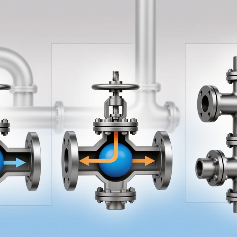
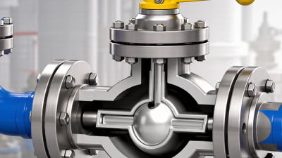
A three-way ball valve routes fluid through three ports using a drilled ball inside its body. Turning the stem changes which ports connect. The two common bore patterns are L-port and T-port. An L-port ball connects a shared port to one branch at a time, making it useful for diverting flow between two lines. A T-port ball can connect all three ports or direct flow between selected ports, depending on its position and design. That distinction matters. Port labels alone may not show every available flow path, so check the valve’s diagram before installation.
These valves are also classified by duty: diverting sends one inlet flow to either outlet, while mixing combines two inlet streams into one outlet. The U.S. Department of Energy’s 2006 Improving Pumping System Performance sourcebook estimates that pumping systems use nearly 20% of global electrical energy. That figure is not specific to valves, but it shows why correct flow routing and sizing matter in pump systems. A valve that restricts flow can affect operating conditions. For selection, verify the port arrangement, pressure and temperature ratings, and whether manual or automated operation is needed. A neat schematic can still mislead; confirm the actual ball positions.
Top Types of Three-Way Ball Valves: Flow Connectivity
L-port valves typically connect two ports at a time to divert flow. T-port valves can connect two ports for diversion or all three ports for a common flow path. Actual connections depend on the valve’s bore design and handle position.
What Is an L-Port Three-Way Ball Valve?
An L-port three-way ball valve has an internal passage shaped like an L. As the handle turns through 90 degrees, the passage connects the common port to one branch, then to the other. The unused branch is blocked. This makes the valve useful for diverting flow or selecting between two sources. It is not normally intended to blend two inlet streams; a T-port design is better suited to that task. Check the valve’s port diagram before installation. Handle position alone can be misleading.
Inside, the ball’s machined passage must align with the correct ports, while seats seal the blocked route. A small mismatch can cause leakage or restrict flow. That matters. For applicable shell tests, API 598, Valve Inspection and Testing, specifies a test pressure of 1.5 times the valve’s pressure rating at 100°F. This is a test requirement, not permission to operate above the rated limit. In practice, confirm the pressure class, seat material, fluid compatibility, and flow direction with the valve documentation. Some L-port configurations also include a closed position, but not all do. It’s easy to assume. Don’t.
| Valve Type | Typical Flow Paths | Common Function | Typical Applications | Key Selection Consideration |
|---|---|---|---|---|
| L-Port three-way ball valve | Connects the common port to one of the two other ports. Rotating the ball typically switches the flow between two paths; it does not provide a straight-through path between all three ports. | Usually used to divert flow to one of two destinations or select one of two sources. | Switching between supply lines, directing fluid to alternate process branches, and selecting between tanks or circuits. | Confirm the port diagram and handle positions. Standard L-port arrangements generally isolate one branch while connecting the common port to the selected branch. |
| T-Port three-way ball valve | The T-shaped bore can connect different combinations of the three ports, depending on the ball design and rotation position. Some designs allow all three ports to communicate in one position. | Can be configured for mixing, diverting, or flow selection. | Combining two inlet streams, distributing flow among branches, and process systems that need several flow-path options. | Check the manufacturer’s flow-pattern drawing and operating positions; not every T-port valve provides the same connections or shutoff behavior. |
| L-Port diverter configuration | A common inlet is directed to either of two outlets, or a common outlet receives flow from either of two inlets, depending on how the valve is piped. | Provides alternate routing, generally with one selected path open at a time. | Changing between process lines, alternate equipment, or two destinations without installing separate manual valves. | Verify that the valve’s allowable position sequence prevents unwanted cross-flow during switching. |
| T-Port mixing configuration | Two inlet ports may be connected to a common outlet in a suitable T-port arrangement. | Combines streams when the valve’s internal porting and system design permit it. | Blending or combining compatible fluids in low-pressure or process piping systems designed for this purpose. | A three-way ball valve does not automatically control mixing proportions; flow balance depends on the system and valve characteristics. |
| T-Port diverting configuration | A common inlet may be routed to one branch or, in certain positions and designs, to both branches. | Distributes a stream to alternate or multiple outlets according to the valve’s port pattern. | Branch-line routing and process changeover where more than one flow pattern is required. | Confirm which ports are connected in every operating position, especially when simultaneous flow to branches is not acceptable. |
What Is a T-Port Three-Way Ball Valve?
A T-port three-way ball valve has a T-shaped passage through its rotating ball. Turning the stem changes which ports communicate. Depending on the ball design and handle stops, it can divert flow from one inlet to either outlet, combine two streams, or connect all three ports. The last position can create an unintended cross-connection if the piping arrangement is misunderstood. Check the valve’s flow diagram, not just its port labels. Small detail, big consequence.
For a practical example, picture a heating loop with one supply line and two branches. A T-port valve can direct hot water toward either branch; some designs also permit both branches to flow together. That capability is not universal. Confirm each handle position, pressure rating, temperature limit, and seat material against the actual service conditions. The U.S. Department of Energy’s Improving Pumping System Performance: A Sourcebook for Industry reports that pumping systems use 25–50% of energy in certain industrial plant operations. That figure describes whole pumping systems, not valves alone, but it shows why avoidable restriction and poor flow choices deserve attention. I would still verify pressure drop with the system designer; a valve’s port shape alone does not predict performance.
How Do L-Port and T-Port Flow Paths Differ?
L-port and T-port describe the shape of the ball’s internal passage, not the outside appearance of a three-way valve. An L-port ball typically connects the common port to one branch at a time. Turn the handle, and flow switches to the other branch. The unused branch is usually isolated. This makes an L-port useful for diverting flow between two lines or selecting one of two sources.
A T-port passage can connect the common port to both branches at once, depending on the valve’s design and handle position. It can also be arranged to direct flow between different ports. That flexibility suits some mixing and distribution duties, but the exact flow paths vary. The label alone is not enough. Check the port diagram and position chart before installation; port names and handle stops can differ between designs.
A small detail matters: never infer the open ports from handle direction alone. For example, a quarter-turn handle may point toward a closed port, depending on the valve’s layout. Trace the flow path on the drawing, then confirm it against the actual piping. It is easy to treat “L” and “T” as complete instructions. They are not. The piping arrangement, pressure, fluid, and required isolation all matter when choosing between them.
How to Choose the Right Three-Way Ball Valve Type
Choosing a three-way ball valve starts with the flow path, not pipe size alone. An L-port valve usually connects one inlet to either of two outlets, making it useful for diverting flow. A T-port can connect all three ports or route flow between selected ports, depending on its position. Check the port diagram carefully. Handle position can be misleading.
For a mixing line, a T-port may bring two streams together, but confirm the permitted switching positions. For switching between tanks, an L-port may reduce unwanted cross-connection. That distinction matters. Match body and seat materials to the fluid, temperature, pressure, and cleaning method. Also consider manual or actuator operation; available space and torque needs differ. Do not size by nominal pipe diameter alone. Flow capacity and pressure drop affect performance.
Before ordering, sketch each required flow state and label every port. Compare the sketch with the configuration drawing, and check how the valve seals in each position. Confirm pressure and temperature ratings for actual service conditions, not just ideal test data. A small mismatch can create dead legs or interrupt supply. Selection can be messier than catalogs suggest, so leave time to verify the details.
Related Posts
-
Why Choose a 3 Way Ball Valve for Global Sourcing?
-
Why Choose a 3 Way Ball Valve?
-
What Is a 3 Way Ball Valve and How Does It Work?
-
China Top 10 3 Way Ball Valve Manufacturers?
-
Top Strategies for Enhancing Efficiency with Pneumatic Valves in Industrial Applications
-
Discover Top Quality Electric Valves from Leading Manufacturers in China