What Is a 3 Way Ball Valve and How Does It Work?
A 3 way ball valve directs, mixes, or isolates fluid through three connected ports. Its internal ball rotates inside the valve body, changing the flow path with a quarter-turn. In a plant, that movement may send chilled water toward a heat exchanger, blend return water, or isolate one branch for maintenance. Simple geometry. Serious consequences.
The global industrial valves market reached approximately USD 78.5 billion in 2023, according to Grand View Research’s Industrial Valves Market Size, Share & Trends Analysis Report. The report also forecasts continued growth through 2030, driven by water treatment, energy, chemical processing, and manufacturing. These figures cover many valve types, not only 3 way ball valve products. That distinction matters.
Greg McMillan, a recognized process-control engineer and author, states, “The control valve is the final control element in most process control loops.” His observation highlights a practical truth: valve selection affects the entire control system. Port arrangement, flow coefficient, actuator response, pressure rating, and sealing material must match the application. A valve can look correctly sized and still perform poorly.
Real systems are messier.
This guide explains how a 3 way ball valve works, including its L-port and T-port configurations, operating positions, and common installation errors. It also considers manual and actuated designs, leakage risks, maintenance access, and control accuracy. Published market data offers useful context, but it cannot replace site-specific engineering calculations. That limitation deserves attention. Temperature changes, fluid chemistry, cycling frequency, and poor alignment may alter performance more than a product brochure suggests.
What Is a Three-Way Ball Valve?
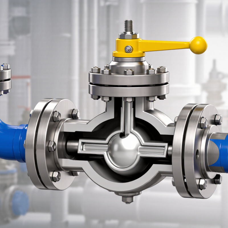
A three-way ball valve is a flow-control device with three connected ports. Its central ball contains an internal passage that redirects fluid between these ports. Turning the stem usually rotates the ball by 90 degrees. The valve can then divert one inlet toward two outlets, or combine two streams into one outlet. It can also isolate a circuit.
A T-port ball valve supports several flow paths. An L-port design normally transfers fluid between two ports. However, port patterns differ among manufacturers and applications. Never rely on the handle position alone. Check the flow diagram. A stainless-steel body may suit corrosive service, while PTFE seats often support moderate temperatures. Pressure, temperature, fluid cleanliness, and seal compatibility still control the final selection.
The industrial valve market exceeded 75 billion U.S. dollars in 2023, according to Global Market Insights’ 2024 industry assessment. That figure covers many valve types, but it reflects strong demand across processing, water, energy, and manufacturing systems. ASME B16.34 provides pressure-temperature requirements for many valve constructions, while ISO 5211 addresses actuator mounting interfaces. Neither standard replaces application testing. A small mismatch can cause leakage, poor mixing, or unexpected shutdowns. This is where specifications sometimes look complete, yet remain incomplete. The actual piping layout deserves equal attention.
| Data Dimension | Key Information | How It Works or Why It Matters |
|---|---|---|
| Definition | A three-way ball valve is a quarter-turn valve with three connection ports and a drilled ball inside the valve body. | Rotating the ball by 90 degrees changes which ports are connected, allowing the valve to direct, combine, or isolate fluid flow. |
| Number of Ports | Three ports, commonly identified as Port A, Port B, and Port C. | The three-port arrangement enables flow diversion, mixing, or selection between different pipelines. |
| Main Flow Functions | Flow diversion, flow selection, flow mixing, and line isolation. | One inlet can be connected to either of two outlets, or two inlets can be connected to one outlet, depending on the ball design and valve configuration. |
| Common Ball Patterns | L-port and T-port. | The internal passage pattern determines which ports communicate at each handle position. |
| L-Port Configuration | The ball has an L-shaped passage. | It normally connects one port to one of the other two ports. It is commonly used for diverting flow or selecting between two lines. |
| T-Port Configuration | The ball has a T-shaped passage. | It can connect different combinations of ports and may allow mixing or distribution. The exact flow paths depend on the valve design and permitted handle positions. |
| Operating Motion | Quarter-turn operation, generally requiring a 90-degree rotation between principal flow positions. | A handle, actuator, or gearbox rotates the stem, which turns the ball inside the valve body. |
| Typical Actuation | Manual lever, electric actuator, pneumatic actuator, or hydraulic actuator. | Manual handles are suitable for local control, while actuators support remote, automated, or repeatable operation. |
| Flow Direction | Flow direction is determined by the selected port connection and the internal passage geometry. | Unlike a simple two-way valve, a three-way valve can redirect flow among three connected lines. |
| Shutoff Capability | Many three-way ball valves can isolate one or more flow paths, but the available shutoff functions depend on the port pattern. | Port configuration and seat design must be checked before using the valve for a specific isolation requirement. |
| Valve Body Shapes | Common body arrangements include horizontal side-entry, vertical-bottom-entry, and compact multi-port designs. | The body layout affects installation orientation, piping arrangement, maintenance access, and actuator clearance. |
| Common Connection Types | Threaded, flanged, socket-weld, butt-weld, and other connection styles may be available depending on the valve design. | The connection must match the pipe size, pressure class, material, installation method, and applicable piping standards. |
| Typical Materials | Valve bodies may be manufactured from brass, bronze, stainless steel, carbon steel, or other alloys. Seats are often made from polymers or engineered materials. | Material selection depends on fluid compatibility, temperature, pressure, corrosion resistance, and required service life. |
| Typical Media | Water, air, gases, oils, chemicals, and other compatible fluids. | The valve must be selected according to the medium's chemical compatibility, cleanliness, temperature, pressure, and viscosity. |
| Common Applications | Process piping, heating and cooling systems, tank filling and draining, bypass circuits, water treatment, and fluid distribution. | Three-way ball valves are useful where one pipeline must be switched between two destinations or several flow paths must be combined. |
| Pressure and Temperature Ratings | Pressure and temperature ratings are design-specific and vary with the body material, seat material, connection type, size, and applicable standard. | Always use the manufacturer's certified rating and derating information rather than assuming a universal pressure or temperature limit. |
| Flow Characteristics | Ball valves generally provide a relatively low flow resistance when the selected passage is fully open. | The full-bore or reduced-bore design, passage shape, and flow path influence pressure loss and flow capacity. |
| Advantages | Compact design, quick operation, low operating effort, reliable switching, and multiple flow-control functions. | One valve can perform routing or mixing duties that might otherwise require several two-way valves and additional piping. |
| Limitations | Incorrect port selection can create an unintended flow path, and some configurations are not suitable for throttling service. | The valve should be operated only in the positions permitted by its design, especially when preventing cross-flow or deadheading is important. |
| Throttling Service | Some three-way ball valves can regulate flow, but standard on/off ball valves are primarily intended for isolation or switching. | Continuous throttling may increase turbulence, wear, noise, and seat damage unless the valve is specifically designed and rated for control service. |
| Installation Considerations | Verify the flow diagram, port labels, handle orientation, pressure rating, temperature rating, and actuator operating limits. | Correct installation prevents reversed flow functions, accidental isolation, actuator interference, and unsuitable loading on the valve. |
| Maintenance Requirements | Inspect for leakage, verify handle or actuator movement, check external connections, and follow the applicable maintenance schedule. | Clean operating media, compatible materials, and correct operating torque help extend valve service life. |
| Selection Checklist | Consider port pattern, valve size, connection type, body and seat materials, pressure, temperature, medium, flow capacity, and actuation method. | A valve is suitable only when all operating conditions and required flow paths are compatible with its technical design. |
Related Posts
-
Why Choose a 3 Way Ball Valve?
-
China Top 10 3 Way Ball Valve Manufacturers?
-

What Defines an Actuated Ball Valve and Its Importance in Industrial Applications
-

7 Essential Benefits of Using High Pressure Ball Valves in Industrial Applications
-
What Makes a Pneumatic Ball Valve the Best Choice for Industrial Applications
-
Exploring the Impact of Motorized Valve Technology on Energy Efficiency in Industrial Applications