
7 Tips for Buying the Best Rotary Sensors
Rotary Sensors turn shaft movement into usable feedback, helping motors, steering systems, and industrial equipment track position and speed. Yet choosing one is rarely a matter of matching a catalog number. A sensor that works smoothly on a test bench may struggle with vibration, heat, electrical noise, or limited installation space. Small details matter.
Industry reports can help frame the decision. Grand View Research’s Rotary Encoder Market analysis and MarketsandMarkets’ Position Sensor Market report examine demand across applications and sensor technologies. Their market-level findings offer context, not a guarantee that any model will suit a particular machine. Buyers still need to check measurable specifications, environmental ratings, interface compatibility, and lifecycle support.
Jacob Fraden, author of Handbook of Modern Sensors, defines a sensor as “a device that receives and responds to a signal or stimulus.” That simple definition points to the real buying question: does the sensor respond accurately under your operating conditions? Start with the required angle range, resolution, accuracy, and output type. Then consider contact versus non-contact designs, mounting tolerances, sealing, and calibration needs. Ask suppliers for test conditions behind their specifications. Numbers can look reassuring.
A careful comparison also accounts for installation and maintenance. A compact magnetic encoder may fit a tight assembly, while a rugged optical unit may better suit a controlled environment. Neither is automatically best. Even experienced buyers can overlook wiring or shaft alignment. These seven tips offer a practical way to assess trade-offs, verify claims, and choose Rotary Sensors with fewer surprises.
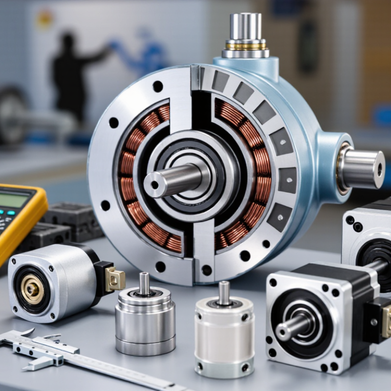
Identify the Application and Required Measurement Range
Before comparing rotary sensors, define what the machine needs to measure. A joint that turns through 90 degrees has different needs from a motor shaft rotating continuously. Note whether the sensor must track position, speed, or both. These details shape the required measurement range and output.
Measure the full mechanical travel, including any overrun during startup or stopping. A sensor with too little range may lose position information; one with far more range may add cost without helping. Check the required angular resolution, too. If a valve moves in small increments, coarse readings can make control uneven. For a high-speed shaft, confirm the sensor can keep up with the rotation rate. Small details matter.
Then consider the installation. A compact sensor may fit near a hinge, while a long shaft or limited mounting space can change the choice. Dust, vibration, and temperature shifts may also affect performance, so compare the operating conditions with the sensor’s specifications. I have seen range selected from a nominal drawing, only for a linkage to travel farther under load. That assumption is easy to miss. Verify the real motion on the machine, if possible, and leave a sensible margin without guessing wildly.
Compare Rotary Sensor Technologies and Operating Principles
Rotary sensors turn shaft movement into electrical information, but they do not all measure it the same way. A potentiometric sensor uses a wiper moving across a resistive track. Its output changes with angle, making the principle easy to understand and often economical. The contact also wears, especially when vibration keeps the shaft moving around one position. Simple, but not wear-free.
Optical encoders read patterns on a rotating disk. Incremental versions produce pulses for a controller to count; an index mark can provide a reference. Absolute optical encoders report a coded position directly, even after power returns. They can offer fine resolution, though dust, condensation, or poor alignment may affect the optical path.
Magnetic sensors detect changing fields from a magnetized target, using Hall-effect or magnetoresistive elements. They tolerate dirt and many harsh conditions, but nearby magnetic fields and mounting gaps deserve attention.
Inductive resolvers use electromagnetic coupling and suit demanding environments; interpreting their signals usually requires more circuitry.
Compare the operating principle with the actual motion. Does the shaft rotate continuously, reverse often, or stop at one angle? Check resolution, repeatability, response speed, temperature range, and output type. A 12-bit label alone does not guarantee useful accuracy.
On a test bench, measure the sensor through its full travel, then repeat after warm-up. A clean datasheet comparison can still mislead.
I would also question whether the installation can hold the specified alignment; real brackets flex a little.
Evaluate Accuracy, Resolution, Linearity, and Repeatability
A rotary sensor’s accuracy tells you how closely its reported angle matches a trusted reference. Resolution is different: it is the smallest change the sensor can distinguish, not proof that the reading is correct. A sensor may display 0.01° steps yet drift from the reference across its travel. Check the specified conditions, too. Temperature, shaft speed, and mounting alignment can change real-world performance.
Linearity describes how consistently output tracks angle across the full rotation. Ask for the error curve, not only a single headline figure. A unit might be close near zero but deviate near 180°. Repeatability shows whether it returns to the same reading when the same position is measured again. Test this with repeated approaches from both directions; backlash or coupling play can disguise the sensor’s own performance. Small details matter.
For a practical comparison, record reference angle, sensor output, direction, and temperature at several points. NIST Technical Note 1297, Guidelines for Evaluating and Expressing the Uncertainty of NIST Measurement Results, explains combining independent uncertainty components using a root-sum-square method. That is useful when judging whether reference equipment and sensor errors together fit your tolerance. Do not treat a datasheet value as a guarantee. A clean bench test can still miss vibration, cable movement, or a poorly secured shaft. I would leave room for that uncertainty.
7 Tips for Buying the Best Rotary Sensors - Evaluate Accuracy, Resolution, Linearity, and Repeatability
| Tip | Evaluation Dimension | What to Check | Useful Evidence or Calculation | Why It Matters |
|---|---|---|---|---|
| Tip 1 | Accuracy | Check the maximum difference between the indicated angle and a traceable reference angle across the specified operating range. Confirm whether the quoted accuracy includes calibration error, temperature effects, and other error sources. | Look for a clearly stated limit, such as ±degrees or ±% of full scale, plus the test conditions. For an angular range of 360°, 0.1% of full scale corresponds to 0.36°. | Accuracy describes closeness to the true or reference angle. A stated value is difficult to compare unless its range, units, and conditions are defined. |
| Tip 2 | Resolution | For a digital sensor, check the number of output bits and whether the quoted resolution is nominal or usable. For an analog sensor, check the smallest reliably detectable change in the complete measurement system. | For an ideal 12-bit absolute output over 360°, the nominal step is 360° ÷ 4096, or about 0.088° per count. Actual measurement performance can be worse because of noise and other errors. | Resolution is the smallest output increment; it is not the same as accuracy. More bits do not by themselves guarantee a more accurate measurement. |
| Tip 3 | Linearity | Ask how the sensor’s output is compared with a reference line or ideal transfer function, and whether the result is specified over the full range or a smaller range. | Check the maximum deviation and its units, commonly degrees or percent of full scale. Confirm whether the specification is independent linearity or uses a best-fit reference line. | Linearity describes how consistently output follows the stated input-output relationship. Different reference-line methods can produce different reported values. |
| Tip 4 | Repeatability | Check repeated readings at the same angle under the same conditions. Review the number of repetitions, approach direction, warm-up state, and whether the result is a range or statistical measure. | Look for a stated repeatability limit in degrees, or for the measurement spread and method used to calculate it. Do not treat repeatability as a substitute for accuracy. | A sensor can return nearly identical readings each time yet still have a consistent offset from the true angle. |
| Tip 5 | Hysteresis and direction effects | Compare readings at the same angular positions while approaching from clockwise and counterclockwise directions. Check for mechanical backlash or direction-dependent output. | Request the maximum difference between readings at the same position for the two approach directions, stated in degrees and under defined test conditions. | Direction-dependent differences can affect positioning systems that reverse direction frequently. |
| Tip 6 | Operating conditions | Match the sensor’s specified temperature range, vibration and shock limits, ingress protection, supply voltage, and mounting requirements to the application. | Review the published environmental limits and the conditions used for performance specifications. Check the datasheet for temperature-related error or drift where relevant. | Performance measured under one set of conditions may not represent performance in the final installation. |
| Tip 7 | Output, interface, and calibration | Confirm that the output type, electrical interface, measurement range, zero position, direction convention, and update rate are compatible with the control system. | Check the output protocol or signal range, wiring requirements, calibration procedure, and any available test or calibration documentation. | A sensor with suitable measurement performance still needs to integrate correctly and maintain the required reference position in the application. |
Note: Specifications and test methods vary by sensor type and manufacturer. Compare values only when their units, measurement ranges, reference methods, and test conditions are clearly defined.
Check Mechanical, Environmental, and Electrical Compatibility
A rotary sensor should match the mechanism it measures, not just its advertised range. Check shaft diameter, mounting pattern, rotation limits, and coupling style against the actual assembly. Even a small mismatch can add play or side load, which may distort readings or shorten service life. Fit matters. Leave room for cables and tools, too; cramped installations can turn routine adjustments into awkward work.
Environmental compatibility deserves equal attention. Note the expected temperature range, humidity, dust, vibration, and possible splashes near the sensor. A unit used beside a warm motor may face very different conditions from one on a protected test bench. Check the enclosure rating against the real exposure, not an idealized one. Seals can help, but they do not make every installation safe from moisture or debris.
Then verify electrical requirements. Compare supply voltage, output type, signal range, connector pinout, and controller input before ordering. An incremental output and an absolute output solve different problems, so confirm how the system needs position reported after power loss. Cable length and electrical noise also matter, especially near motors or switching equipment. It is tempting to prioritize resolution, but resolution alone does not guarantee useful accuracy. Recheck the full setup with the machine’s actual load and wiring; early assumptions sometimes miss a constraint.
Assess Durability, Calibration Needs, Support, and Total Cost
Durability starts with the conditions around the shaft. Check the sensor’s rated temperature, vibration tolerance, and resistance to dust or moisture. A unit near a hot motor may need different protection than one inside a clean control cabinet. Details matter. Also inspect connector strain relief and mounting hardware; small weaknesses can cause intermittent readings after repeated vibration. Ask for documented test conditions, not just a broad “industrial grade” claim.
Calibration needs affect both accuracy and upkeep. Confirm the required angular range, resolution, linearity, and drift over time. Then ask whether calibration is factory-set, field-adjustable, or dependent on specialized equipment. A sensor that meets the specification on paper may still need frequent checks in your actual setup. That can mean downtime. Support matters here: clarify response times, access to setup guidance, replacement availability, and how technical questions are handled. A clear manual and a real troubleshooting path can save hours during commissioning.
Compare total cost over the expected service life, not only the purchase price. Include installation labor, calibration intervals, connectors, protective housings, and potential downtime. A lower-cost sensor may be sensible for an easy-to-reach test rig, but less so on a machine that runs continuously. One assumption worth challenging is that greater precision always pays off. If the application cannot use that extra accuracy, you may be paying for performance you do not need.