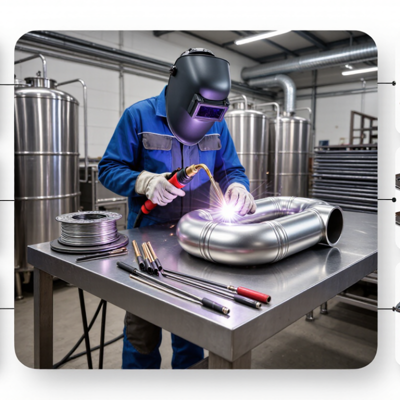
How to Weld 304 Stainless Steel Properly?

Welding 304 Stainless Steel demands more than heat and filler metal. This widely used austenitic grade resists corrosion, forms cleanly, and appears in food equipment, chemical vessels, architectural parts, and process piping. Yet its forgiving reputation can mislead inexperienced welders. Excessive heat may cause distortion, discoloration, warping, or reduced corrosion resistance near the joint.

Dr. John C. Lippold, a recognized authority in stainless steel welding, has written, “Welding is a complex process involving thermal, metallurgical, mechanical, and chemical interactions.” That principle guides this article. Proper results depend on joint preparation, shielding gas, amperage, travel speed, filler selection, and post-weld cleaning. A bright bead is not always a sound bead. Appearance can deceive.

This guide explains how to weld 304 stainless steel properly using practical workshop controls. It covers TIG, MIG, and related preparation methods. You will see why stainless steel brushes must remain dedicated to stainless work. You will also learn how heat input affects sensitization, distortion, and the passive surface layer. Small details matter. Keep the tungsten sharp. Protect the backside. Remove oxide stains carefully.

Some recommendations vary with thickness, joint design, and equipment. There is no single perfect setting. That uncertainty deserves attention. Even experienced welders may overheat a thin 304 panel or overlook contamination from carbon-steel tools. The safest approach combines qualified procedures, clean materials, controlled technique, and inspection. Welding 304 Stainless Steel becomes reliable when metallurgy and hands-on discipline work together.

How to Weld 304 Stainless Steel Properly?

304 Stainless Steel Properties and Weldability Requirements

304 stainless steel contains approximately 18% chromium and 8% nickel. This austenitic structure gives it good corrosion resistance and reliable toughness. It also makes 304 relatively easy to weld. However, welding changes its surface and heat-affected zones. Excessive heat can cause distortion, oxidation, and reduced corrosion performance. In some conditions, chromium carbides may form near grain boundaries. This risk increases when the material stays hot for too long. Using 304L filler or base material can reduce sensitization because of its lower carbon content. A perfect-looking bead can still hide contamination or poor shielding.

Tips: Clean the joint with a dedicated stainless-steel brush and solvent. Keep carbon-steel tools away from the prepared surface. Use stable shielding gas coverage, short arc lengths, and controlled heat input. Tack welds should be evenly spaced. Allow cooling between passes.

For TIG welding, a sharp tungsten and a clean, dry gas line help produce a narrow, controlled bead. Keep the torch angle steady and protect the weld until it cools below visible oxidation temperatures. For MIG welding, consistent wire feeding and correct gas flow are essential. Excessive flow can create turbulence, not better protection. I have found that operators often focus on bead appearance and overlook the back side. Purging the root is important for pipe and thin-sheet work. After welding, remove heat tint and inspect the joint under strong light. Sometimes the process needs adjustment. That is normal.

Essential Tools, Materials, and Safety Preparations

How to Weld 304 Stainless Steel Properly?

Welding 304 stainless steel starts with controlled preparation. I use a TIG welder for clean, precise joints and stable heat control. For filler metal, ER308L usually matches 304 stainless well. Use high-purity argon, a suitable tungsten electrode, and a clean gas cup. Keep a dedicated stainless-steel brush nearby. Never share it with carbon steel tools.

Cleanliness matters greatly. Remove oil, fingerprints, and oxide marks with a suitable solvent before welding. Fit the parts tightly, then secure them with stainless-compatible clamps. Thin sheet can distort quickly. Short tack welds help limit movement. For pipe or enclosed joints, an argon back purge protects the inside from heavy oxidation. Keep the gas flow steady, not excessive. Too much gas may create turbulence.

Wear a properly rated helmet, flame-resistant clothing, gloves, and closed footwear. Provide effective ventilation because welding fumes can harm your lungs. Remove flammable materials from the work area, and keep suitable fire-control equipment accessible. Check cables, connections, and shielding gas lines before striking an arc. I usually test settings on scrap 304 first, since identical thicknesses can still react differently. I still occasionally overheat a corner when moving too slowly. That mistake reminds me to watch the weld pool, reduce amperage, and allow cooling between passes. Thin metal needs patience. Clean each pass carefully, inspect for cracks or discoloration, and avoid grinding away too much material.

How to Prepare and Fit 304 Stainless Steel Joints

How to Weld 304 Stainless Steel Properly

Preparing and fitting 304 stainless steel joints often determines the weld quality before the arc starts. Cut the edges cleanly, then remove oil, scale, and fingerprints with a suitable solvent. Use stainless-only brushes and tools. Shared carbon-steel tools can leave iron particles that later cause surface rust.

Keep the joint gap consistent and align the parts without forcing them together. Excessive pressure can release the fit during heating. For butt joints, maintain a small, even root opening based on the approved welding procedure. Tack welds should be short, evenly spaced, and placed to control distortion. Check alignment after each tack. Small errors grow quickly.

Back-purge the joint when the rear side must remain smooth and corrosion resistant. Shielding gas coverage matters. Drafts, loose hoses, or poor cup positioning can contaminate the weld. Use controlled heat input, because 304 stainless steel expands noticeably and retains heat. A qualified welder should select current, travel speed, filler metal, and gas flow for the joint thickness and position.

Do not trust appearance alone. Inspect the root, edges, and heat-affected area after cleaning. Discoloration is not always harmless. Overheating can reduce corrosion resistance, even when the bead looks attractive. A common shortcut is rushing fit-up to save time. It usually creates more rework. Leave room for correction; perfect alignment is easier to claim than to achieve.

How to Weld 304 Stainless Steel Properly? - How to Prepare and Fit 304 Stainless Steel Joints
Preparation or Fit-Up Item Recommended Practice Typical Value or Target Purpose and Verification
Base Material Confirm that the material is 304 or 304L stainless steel and identify the thickness before selecting the joint design. Common fabrication range: approximately 1.5–12 mm sheet or plate. Material grade and thickness affect filler selection, heat input, distortion, and the required welding procedure.
Joint Cleaning Remove oil, grease, paint, moisture, oxides, and shop dirt from both sides of the joint. Use a dedicated stainless-steel brush or clean abrasive that has not contacted carbon steel. Clean at least 25–50 mm on each side of the joint. Prevents porosity, contamination, arc instability, and embedded iron that can later cause surface rust.
Edge Preparation: Thin Material For thin sheet, use a square-butt joint when full penetration can be achieved without excessive burn-through. Typically up to about 3 mm thickness; joint gap commonly 0–1 mm. Keep the fit-up uniform and use low heat input. Confirm penetration on a test coupon when the joint is critical.
Edge Preparation: Medium Thickness Use a single-V groove for thicker material when a square edge cannot provide reliable full penetration. Typical included angle: 60–70°; root face: 1–2 mm; root opening: 1–3 mm. These are practical starting dimensions. Final values should follow the qualified welding procedure and applicable code.
Edge Preparation: Heavy Section For thicker sections, use a double-V, U-groove, or another balanced preparation when access is available from both sides. Often considered above approximately 10–12 mm; use balanced grooves to reduce weld volume and distortion. Back-gouge or back-grind the first side to sound metal before welding the second side.
Root Gap Set the root opening with clean, consistent spacers or calibrated fit-up tools. Avoid forcing parts together during welding. Common starting range: 1–3 mm for a manually welded open root, depending on thickness and process. A gap that is too small can cause incomplete penetration; an excessive gap increases burn-through, filler use, and distortion.
Root Face Keep the root face even around the joint and remove sharp burrs after cutting or machining. Typical root face: 1–2 mm for a single-V groove. Uniform land thickness helps control penetration and reduces the risk of a locally excessive weld pool.
Joint Alignment Align the parts before tacking and prevent high-low mismatch. Use temporary fixtures that allow thermal expansion. Keep mismatch as low as practical; a common fabrication target is about 10% of the thinner wall thickness, subject to the governing specification. Excessive offset creates stress concentration and uneven penetration. Measure with a straightedge, bridge gauge, or suitable fit-up gauge.
Joint Restraint Use balanced clamping and tack-weld sequencing rather than excessive restraint. Do not use galvanized or contaminated clamps at the weld area. Use evenly spaced tacks sized for the thickness; remove cracked, porous, or contaminated tacks completely. Balanced restraint limits distortion while still allowing controlled shrinkage during cooling.
Filler Metal For standard 304 stainless-steel joints, select a compatible low-carbon austenitic stainless filler. Common choice: ER308L for TIG or MIG welding; use the filler specified by the qualified procedure for the service conditions. The “L” designation limits carbon in the deposited weld metal and helps reduce sensitization risk during thermal exposure.
TIG Shielding Gas Use clean, dry argon with stable coverage. Keep the torch angle low and maintain a short, consistent arc length. Typical argon flow: approximately 7–12 L/min, adjusted for torch, cup size, draft, and joint geometry. Too little gas can cause oxidation and porosity; excessive flow can create turbulence and draw air into the shielding zone.
Back Purging For open-root pipe, tube, or full-penetration joints where the reverse side will be exposed, purge the root with argon. Typical purge flow: approximately 5–12 L/min after the enclosure is displaced; maintain positive, low-turbulence coverage. Back purging prevents heavy oxidation, known as sugaring, which can reduce corrosion resistance and impair root quality.
MIG Shielding Gas Use a qualified stainless-steel GMAW procedure with a low-oxidizing shielding-gas mixture appropriate for the transfer mode. Common starting range: 12–18 L/min; exact composition and flow depend on wire diameter, transfer mode, and equipment. Do not use an unqualified gas or excessive flow. Verify bead shape, arc stability, and porosity on a test piece.
Heat Input Use the lowest heat input that provides complete fusion and penetration. Prefer multiple controlled passes over one excessively hot pass on thick material. Keep travel speed, current, voltage, and pass sequence consistent; avoid prolonged arc stops on thin sections. Lower heat input reduces distortion, discoloration, carbide precipitation risk, and loss of corrosion performance.
Interpass Temperature Allow the joint to cool between passes and monitor the temperature near the weld area. A common control limit is below 150°C between passes unless the qualified procedure specifies otherwise. Low interpass temperature helps limit sensitization, distortion, and excessive heat accumulation.
Tack Welds Place clean, sound tacks symmetrically and fuse their ends into the final weld. Grind out any tack containing cracks or visible contamination. Typical tack spacing: about 50–150 mm, adjusted for joint length, thickness, and distortion risk. Proper tack placement maintains root gap and alignment without creating hard restraint or trapped defects.
Welding Sequence Use a skip, back-step, or alternating sequence where appropriate. Weld from the center outward on long joints when practical. Use short, controlled weld segments on thin sheet; allow cooling between opposing passes. Sequencing distributes shrinkage and helps maintain straightness, root opening, and dimensional accuracy.
Interpass Cleaning Remove slag, oxides, and discoloration between passes using stainless-only tools. Do not weld over visible contamination. Clean until the previous bead and fusion boundaries are clearly visible. Prevents inclusions and lack of fusion, especially when using processes or consumables that produce surface oxides.
Post-Weld Cleaning Remove heat tint and surface contamination by an appropriate mechanical or chemical method, then rinse and dry thoroughly. For corrosion-critical service, restore a clean, passive surface after welding. Heat tint can reduce the corrosion resistance of stainless steel near the weld. Follow the approved safety procedure for any pickling or passivation chemicals.
Visual Inspection Inspect the completed weld for cracks, undercut, overlap, excessive concavity or convexity, arc strikes, porosity, and incomplete fusion indicators. Acceptance limits must come from the applicable drawing, code, or qualified welding procedure. Visual inspection should be completed after cleaning and before painting, insulation, pressure testing, or service.
Technical note: The dimensions and settings above are typical fabrication starting points, not universal acceptance criteria. Final joint preparation, tolerances, filler metal, shielding, heat input, inspection, and acceptance requirements must be established by a qualified welding procedure and the applicable project standard.

Step-by-Step Welding Procedure for 304 Stainless Steel

How to Weld 304 Stainless Steel Properly?

A reliable procedure starts with material verification. ASTM A240 lists 304 stainless steel at approximately 18–20% chromium and 8–10.5% nickel. Clean the joint with acetone and a dedicated stainless-steel brush. Never use carbon-steel tools. Fit the parts tightly, then tack evenly to reduce distortion. GTAW usually uses a sharp tungsten electrode and pure argon shielding. For filler metal, ER308L is commonly selected for 304 joints. Set current according to thickness, joint design, and the qualified welding procedure.

Control heat carefully. The ASM Handbook reports thermal conductivity near 16.2 W/m·K and thermal expansion around 17.2 µm/m·°C for austenitic stainless steel. Heat therefore spreads slowly and distortion can appear quickly. Use short weld runs and steady travel speed. Keep the interpass temperature within the approved procedure, often below 150°C. AWS D1.6/D1.6M emphasizes qualified procedures, suitable filler metals, and inspection requirements. After welding, remove heat tint mechanically or chemically using an approved process. A bright bead is not automatically a sound bead. Root oxidation may remain hidden.

Tips: Shield the weld pool and the hot root. Check gas flow before striking the arc. Excessive flow can create turbulence. Practice on a scrap coupon first, then inspect penetration and discoloration. I still recheck fit-up after tacking; small gaps often become large distortion. Record amperage, travel speed, gas flow, and interpass temperature for repeatable results.

How to Weld 304 Stainless Steel Properly?

Step-by-Step Welding Procedure for 304 Stainless Steel

Typical GTAW starting current for 304 stainless steel: These values are practical starting points for clean, flat-position welding with a DCEN torch and a sharp tungsten electrode. Adjust the current according to joint design, fit-up, welding speed, and heat dissipation.

  1. Clean the joint with a stainless-steel brush and acetone to remove oil, dirt, and surface contamination.
  2. Use a suitable joint fit-up and tack welds to control distortion.
  3. Set the GTAW machine to direct current electrode negative and use high-purity argon shielding gas.
  4. Maintain a short arc length and use a consistent travel speed to limit heat input.
  5. Add 308L stainless filler metal when filler is required for 304 stainless steel.
  6. Allow the weld to cool naturally, then remove heat tint and clean the weld area.

Note: The chart provides general starting values, not a qualified welding procedure specification. Final settings should be verified through a suitable procedure qualification and adjusted for the actual joint.

Post-Weld Cleaning, Inspection, and Common Defect Prevention

How to Weld 304 Stainless Steel Properly?

Post-weld cleaning begins after the joint has cooled naturally. Do not quench hot stainless steel with water. Remove slag, spatter, and discoloration using dedicated stainless-steel tools. Carbon-steel brushes can leave iron particles, which later create rust stains.

For heat tint, use an approved stainless-steel cleaning method, then rinse thoroughly with clean water and dry the surface completely. A bright weld is not automatically a sound weld.

Inspect the bead under strong, angled light. Look for cracks, undercut, overlap, pinholes, excessive oxidation, and uneven penetration. On pipe work, inspect the inside surface too.

Dark, rough “sugaring” often shows poor shielding or insufficient purge gas. Dye penetrant testing can reveal surface-breaking cracks that visual inspection misses.

Record the findings, even when the weld appears acceptable. Small defects are easy to dismiss, and that habit causes repeat failures.

Tips

Keep the joint clean before welding. Use a stable purge setup and verify gas coverage near the root. Limit heat input to reduce distortion and carbide precipitation risks.

If a weld fails inspection, do not simply grind and cover it. Remove the defective area, identify the cause, and repair it under a controlled procedure.

My own review point is simple: cleaning should not be treated as cosmetic work. It directly affects inspection results and service reliability.