
How to Choose the Best Industrial Digital Camera?
Choosing the best Industrial Digital Camera is not simply a resolution contest. It is a decision about light, motion, data, and production risk.
Industry demand is expanding. MarketsandMarkets’ Machine Vision Market report estimated the sector at about USD 13.2 billion in 2023. It projects roughly USD 21.3 billion by 2028. Grand View Research also reports strong growth in industrial cameras through the decade. However, these reports use different market definitions. Their numbers should guide research, not replace it.
Jeff Burnstein, president of the Association for Advancing Automation, describes machine vision as “the eyes of automation.” That image is practical. A camera watches a fast conveyor, detects a scratched metal edge, and sends evidence to a controller within milliseconds. The wrong model may produce blurred images, unstable inspections, or expensive production delays.
A reliable selection process begins with the inspection task. Define the smallest defect, working distance, conveyor speed, field of view, and available lighting. Then compare sensor size, frame rate, shutter type, interface, and software compatibility. A high-megapixel camera can still fail under vibration or poor illumination. More pixels are not always better.
Experience also exposes an uncomfortable truth. Many buyers focus on the camera while underestimating optics and lighting. That mistake can distort an otherwise excellent system. This guide examines the technical and operational factors behind a dependable Industrial Digital Camera choice. It also questions common assumptions, because factory conditions rarely match a clean showroom demonstration.
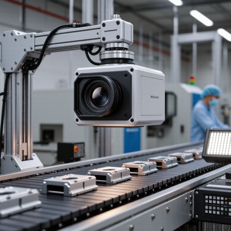
Define the Imaging Requirements for Your Industrial Application
Before choosing an industrial digital camera, define the inspection task in measurable terms. What is the smallest defect? How fast does the object move? What contrast exists between the defect and its background? A scratched metal surface may need 12-megapixel resolution, controlled lighting, and short exposure times. A bottle-counting system may need fewer pixels but higher frame rates. According to Grand View Research, the global machine vision market reached about USD 11.2 billion in 2023, showing how rapidly automated inspection is expanding.
Measure the field of view and calculate pixels per millimeter. A practical target is often 3–5 pixels across the smallest critical feature, although reflective materials may demand more. Choose monochrome imaging for subtle brightness differences, or color imaging when hue identifies defects.
Near-infrared imaging can reveal variations hidden from human vision. It is useful, but not magic. According to the International Federation of Robotics, factories installed more than 541,000 industrial robots in 2023, increasing the need for cameras that maintain accuracy during fast motion.
Environmental details matter just as much. Dust, vibration, heat, washdown routines, and limited installation space affect housing, connectors, and cooling. Confirm whether the camera supports the required exposure control, triggering, data rate, and software integration.
In plant testing, I have seen excellent cameras fail because the lighting changed between shifts. That mistake is easy to repeat. Test real samples, including dirty, scratched, and poorly positioned products, before approving the final specification.
Compare Sensor Types, Resolution, and Image Quality
How to Choose the Best Industrial Digital Camera?
Sensor choice shapes image quality more than headline resolution. CMOS sensors usually provide higher frame rates, lower power use, and easier integration. CCD sensors can still deliver stable images in controlled inspection systems. For moving parts, global shutter prevents bent edges and misplaced holes. Rolling shutter may create distortion under fast conveyor motion.
Resolution must match the smallest defect, not the marketing specification. A useful target is two to four pixels across the defect’s critical width. For example, a 0.2-millimeter scratch needs careful lens and working-distance calculations. More pixels cannot rescue poor lighting or a weak lens. According to the EMVA 1288 measurement standard, dynamic range and signal-to-noise ratio should be checked alongside quantum efficiency. These figures reveal performance in shadows, glare, and uneven surfaces.
Market demand also reflects this shift toward reliable vision systems. Allied Market Research reported that the global machine vision market was valued at about 15.7 billion dollars in 2022 and may reach 35.3 billion dollars by 2032. That growth does not make every high-resolution camera suitable. Test images using the real material, conveyor speed, and exposure time. I have seen a lower-resolution sensor outperform a larger one when its pixels received cleaner light. This is easy to underestimate. Check image data, not just catalog numbers.
How to Choose the Best Industrial Digital Camera?
Compare sensor technologies using representative industrial-camera values for resolution and dynamic range. Higher resolution captures more detail, while higher dynamic range preserves information in both bright and dark areas.
Interpretation: CCD sensors are known for consistent image quality and strong dynamic range. Rolling-shutter CMOS sensors commonly provide high resolution and fast readout at lower system cost. Global-shutter CMOS sensors are preferable for moving objects because they reduce geometric distortion during exposure. Actual performance varies with the selected sensor, pixel size, exposure settings, optics, and lighting.
Evaluate Lens Compatibility, Lighting, and Field of View
Choosing an industrial digital camera starts with the lens, lighting, and field of view. According to the MarketsandMarkets 2023 report, the machine vision market may grow from $30.5 billion in 2023 to $45.7 billion by 2028. That growth reflects stricter inspection needs, not simply higher camera sales.
Check the lens mount, flange distance, sensor format, and image circle. A lens designed for a smaller sensor may create dark corners on a larger one. Measure the object area at the working distance, then calculate field of view before ordering hardware. Leave modest margin for product movement. Too much margin wastes pixels. Too little margin causes missed edges.
Lighting changes the result more than many teams expect. The International Energy Agency reports that LED lighting can use at least 75% less energy than incandescent lighting, making controlled LED illumination practical for continuous inspection. Use diffuse light for reflective metal, angled light for scratches, and backlighting for accurate outlines. Keep exposure, working distance, and light intensity fixed during tests. It sounds obvious.
In practice, lens charts can mislead. A camera may meet its resolution target, yet glare or vibration can ruin the image. I would test real parts, including damaged and slightly misaligned samples, before final selection. The “best” setup is often not the sharpest one, but the most repeatable one.
How to Choose the Best Industrial Digital Camera? - Evaluate Lens Compatibility, Lighting, and Field of View
| Evaluation Dimension | Typical Technical Data | Why It Matters | Selection Guidance |
|---|---|---|---|
| Sensor Format | 1/3 in: approximately 4.8 × 3.6 mm 1/1.8 in: approximately 7.2 × 5.4 mm 2/3 in: approximately 8.8 × 6.6 mm 1 in: approximately 13.2 × 8.8 mm | The sensor format determines the minimum lens image circle and affects the achievable field of view with a given focal length. | Choose a lens rated for the same format or a larger format. A lens designed for a smaller sensor may cause dark corners or vignetting. |
| Lens Mount Compatibility | Common industrial mounts include C-mount and CS-mount. C-mount flange focal distance: 17.526 mm. CS-mount flange focal distance: 12.5 mm. | The mount must match the camera body, and the flange distance must allow the lens to focus correctly. | Do not attach a CS-mount lens directly to a C-mount camera without the correct spacing. A C-mount lens may be used on some CS-mount cameras with an appropriate 5 mm spacer, subject to the camera design. |
| Lens Image Circle | The lens image circle should be equal to or larger than the sensor diagonal. Approximate sensor diagonals: 1/3 in = 6.0 mm; 1/1.8 in = 9.0 mm; 2/3 in = 11.0 mm; 1 in = 15.9 mm. | An insufficient image circle produces vignetting, uneven illumination, and reduced usable image area. | Allow a small margin above the sensor diagonal, especially when the lens is used with an adjustable aperture, close focus, or off-axis illumination. |
| Focal Length and Field of View | Approximate object width: FOV = (Object Distance × Sensor Width) ÷ Focal Length Use consistent units for all measurements. | Focal length controls how much of the target is visible at a defined working distance. Longer focal lengths provide a narrower view. | Measure the required object width and working distance first, then select a focal length that provides the required coverage without excessive digital cropping. |
| Field-of-View Example | A 1 in sensor with a 13.2 mm horizontal width, a 16 mm lens, and a 400 mm working distance gives an approximate horizontal FOV of 330 mm. | A worked estimate helps verify whether the selected camera and lens can cover the complete inspection area. | Allow additional margin for part-position variation, mechanical tolerances, and any region that must be inspected around the target. |
| Resolution and Pixel Coverage | If a 2,000-pixel-wide image covers a 200 mm-wide object, the sampling is approximately 0.10 mm per pixel. | Pixel coverage determines whether small defects, edges, characters, or measurement features can be separated reliably. | Define the smallest feature to detect and provide multiple pixels across it. The required number depends on contrast, optics, focus, and inspection algorithms. |
| Lighting Geometry | Common arrangements: diffuse dome lighting for reflective or curved surfaces; coaxial lighting for flat reflective surfaces; backlighting for silhouettes and dimensional inspection; low-angle lighting for surface texture and scratches. | Lighting direction and diffusion often have a greater effect on inspection reliability than camera resolution alone. | Select the lighting method according to surface finish, defect type, geometry, and required contrast. Use controlled, repeatable illumination rather than relying on ambient light. |
| Exposure and Motion Control | For moving objects, short exposure times reduce motion blur. Pulsed LED lighting can provide high peak brightness for brief exposures while limiting average heat and power. | Motion blur can hide small defects even when the image has sufficient nominal resolution. | Check camera triggering, exposure control, light pulse duration, and the object's speed as one system. Avoid increasing gain as the primary solution for insufficient illumination. |
| Aperture and Depth of Field | A smaller aperture, represented by a higher f-number, generally increases depth of field but reduces the amount of light reaching the sensor. | Parts with height variation may not remain sharp across the entire inspection region at a wide aperture. | Balance depth of field against diffraction, exposure time, and available lighting. Lock the aperture after setup to prevent image-to-image variation. |
| Spectral Requirements | Visible lighting is commonly used for general inspection. Red or near-infrared illumination can improve contrast for selected materials, while ultraviolet requires suitable optics and sensor response. | Different wavelengths interact differently with coatings, inks, plastics, metals, and biological or chemical residues. | Confirm sensor sensitivity, lens transmission, filter compatibility, and operator safety before selecting non-visible illumination. |
| Working Distance and Mechanical Space | Working distance is the distance from the specified lens reference point to the inspected object. Lens specifications may also list a minimum object distance for focusing. | The available installation space may restrict focal length, lighting position, cable routing, and protective housing dimensions. | Verify the real mounting envelope, minimum focus distance, lens barrel clearance, and lighting access before finalizing the camera position. |
| Industrial Environment | Relevant conditions may include dust, moisture, vibration, temperature variation, cleaning fluids, and electromagnetic interference. | Environmental factors can change focus, reduce contrast, damage equipment, or introduce unstable image output. | Specify suitable enclosure protection, lens protection, vibration support, thermal management, and cable shielding for the installation site. |
| Recommended Verification Test | Test the complete camera, lens, lighting, trigger, and processing configuration using production parts and the actual mounting distance. | Specification sheets cannot fully predict glare, reflections, vibration, part variation, or algorithm performance in a real production environment. | Validate FOV, sharpness, illumination uniformity, exposure stability, defect contrast, repeatability, and cycle time before deployment. |
Assess Speed, Connectivity, Software, and System Integration
Choosing the best industrial digital camera requires more than comparing resolution. Speed, connectivity, software, and system integration determine daily performance.
Measure real throughput under production conditions. A high frame rate means little if the camera drops images during continuous operation. Check trigger latency, exposure time, and sustained data transfer. Test moving parts, changing light, and vibration. I once trusted a short laboratory test and underestimated heat buildup during an eight-hour shift. That mistake changed the evaluation process.
Connectivity should match the machine’s control architecture. Common interfaces include GigE, USB3, and CoaXPress, but each has different cable lengths, bandwidth limits, and installation demands. Confirm connector durability and reliable data transmission near motors or welding equipment. Plan for synchronization with encoders, sensors, and programmable controllers. A fast camera cannot repair unstable network timing.
Software often decides whether integration feels simple or painful. Look for stable drivers, clear documentation, software development kits, and support for standard image-processing libraries. Test camera settings through the actual inspection program, not only the manufacturer’s utility. The interface may look convenient, yet lack remote diagnostics or fault logging. That becomes expensive later. Consider processing requirements too. Edge processing can reduce network traffic, while centralized processing may simplify updates. I still leave extra bandwidth and computing capacity, because early estimates are rarely perfect.
Verify Durability, Compliance, Support, and Total Cost of Ownership
How to Choose the Best Industrial Digital Camera?
Industrial camera selection should begin with the production environment, not pixel count. The International Federation of Robotics reported 541,302 industrial robot installations worldwide in 2023. That growth increases demand for stable machine vision. A camera near a conveyor may face vibration, dust, oil mist, heat, and repeated cleaning. Check the IP rating under IEC 60529, operating temperature, shock resistance, and connector protection. Also verify electromagnetic compatibility against applicable IEC 61000 requirements. A laboratory specification is not enough.
Compliance needs practical evidence. Request test reports, declarations, firmware security details, and traceable calibration records. Support matters just as much. Ask about spare units, repair times, software updates, and integration assistance. Deloitte’s 2023 Smart Manufacturing and Operations Survey found that 86% of manufacturers expect smart manufacturing to drive competitiveness within five years. Yet digital equipment can still become an expensive bottleneck. I have seen teams choose higher resolution, then discover that lighting, lenses, and network bandwidth created the real delay. That mistake is easy to repeat.
Tips: Calculate total cost of ownership over five years. Include lenses, lighting, cables, software licenses, calibration, training, energy, and downtime. Compare the expected failure rate, replacement time, and image quality under real conditions. Test one camera beside the actual machine. The test may expose weak mounting, glare, or heat that brochures never mention. A lower purchase price can become costly when support is slow. I would also document assumptions, because early estimates are often imperfect.